TheGreydiamonds Blog

Tag: smarthome

Reverse engineering a Moonside Lighthouse Light

Working in Progress

This article is still a work in progress, which means it will be updated in the future. Images may be missing captions or alt-texts. There might also be some language weirdness.

I’ve had a Moonside Lighthouse lying around for some time. It’s a pretty nice-looking light fixture, however, there was no way to integrate it into my Homeassistant setup. I’ve had a shot at reverse engineering it’s communication and here are my results:

Trying the network route

Lighthouse is able to join your WiFi-Network for remote control, because of that I was hoping to find some open network port using Nmap. A quick scan showed nothing, meaning that this way is likely a dead end.

However, this digging surfaced one interesting piece of information about its MAC Address, which belongs to the Espressif MAC range (meaning it’s likely something ESPy).

Internet

There also exists a public API which enables you to control the fixture remotely. I was unable to get it working, also I would like to be able to control my light locally. I have not explored this route further.

Bluethooth

After it became clear that networking is sadly not an option I started looking into Bluethooth. The App uses BLE to talk to the lamp. My first attempt was to use the nRF Connect tool to reads its characteristics.

A screenshot made in the nRF connect app showing three services. The first being a "Generic Attribute" with UUID: 0x1801.
The next one being a "Generic Access" with the UUID 0x1800.
The last one is "Nordic UART Service" with UUID: 6e400001-b5a3-f393-e0a9-e50e24dcca9e
A screenshot from the nRF connect app where the first service ("Generic Access") was expanded. It's shows three attributes, "Device Name", "Apperance" and "Central Address Resolution". The device name is "MOONSIDE-T1", apperance is "[0] Unknown", address resoultion is not supported.

None of these characteristics were helpful, except one which piqued my interest., “Nordic UART Service”, I’ve never heard of that before, though it seems fairly helpful. Using the nRF toolbox I was able to connect to it via BLE UART. That itself worked fine, however, brute-forcing commands were not useful as there was no response to anything.

Snooping the traffic

The next logical step was to snoop on the traffic between the android app and the hardware counterpart. That proved to be not as easy as it sounds, in the end, I used Wireshark to look at the traffic.

First step was to enable Bluetooth Snooping in the developer settings. Then after some debugging and using this command:

db shell su -c "'nc -s 127.0.0.1 -p 8872 -L system/bin/tail -f -c +0 data/misc/bluetooth/logs/btsnoop_hci.log'"

The interface showed up in Wireshark. Though you need to android dump androiddump module for Wireshark.

Info

It seems like your device needs to be rooted for this to work, I’ve seen contradicting information about that, however.

Finally, I was able to see communication with a device called Espressi_2a:9d:5a, which looks suspiciously like the device in question.

Deconstructing the communication

The became apparent that the app talks in clear text with the light fixture. These commands started showing up:

CommandDescription
LEDOFFTurns the light off
LEDONTurns the light on
BRIGHXXXBrightness, replace XXX with number (max: 120, min:0)
COLORRRRGGGBBB XXXSets the colour, replace R with red value, G with green value and B with blue value (0-255), optional X brightness argument
THEME.????????Sets a theme
PIXEL,ID,XXX COLOR?Set a pixel, where ID is the pixel (0-89), XXX is the brightness and COLOR is the colour in an unknown format
MODEPIXELApplies pixel settings

Mind you the values of for example the ID range might be different between devices, however I will probably not buy more devices just to prove my theory.

Some things are also just unknown. I do not understand how sound-enabled modes work (yet!). It sends some number string and that’s it. I was also unable to figure out the COLOR format for pixel setting, it is six digits ranging from 0-9.

Themes

Themes are a whole different topic. They are way more configurable than the app gives you options. Here is a list of the themes from the app:

Theme nameThemenick
RAINBOW1.20,Rainbow One
FIRE1.20,Night Fire
THEME.THEME1.162,255,174,255,85,90,Blue Raspberry
THEME.WAVE1.255,0,0,255,0,255,Pink Ball
THEME.BEAT1.255,0,0,0,255,0,0,0,255,Dancing Beat
THEME.GRADIENT2.0,255,0,20,65,20,200,200,200,Green Land
THEME.THEME3.0,0,200,0,100,200,100,0,200,200,0,0,200,06,100,120,200,0,Candy Mix
THEME.THEME1.255,0,0,0,0,255,My Moon
THEME.BEAT2.255,255,0,0,0,255,Bouning Stars
THEME.GRADIENT1.0,255,0,255,0,0,Christmas Blend
THEME.RAINBOW3.0,Blending Rainbow
THEME.THEME2.138,35,135,242,113,33,Wire Tap
THEME.COLORDROP1.10,100,255,200,200,200,Raining Blue
THEME.TWINKLE1.255,0,0,0,0,255,Twinkle Star
THEME.FIRE2.0,0,0,0,255,0,200,0,0,255,0,0,Green Fire
THEME.GRADIENT2.145,3,245,255,25,194,191,176,187,Purple Cake
THEME.GRADIENT1.150,0,255,255,214,243,Purple Dream
THEME.LAVA1.200,0,0,50,0,0,0,0,255,Blue Lava
THEME.LAVA1.20,255,2,255,100,0,255,0,60,MacMac
THEME.THEME1.168,255,120,120,255,214,Summer Glow
THEME.BEAT2.7,200,249,13,34,135,Dancing Ocean
THEME.PALETTE2.0,0,200,0,100,200,100,0,200,200,0,0,2006,0,100,120,200,0,Colorful Swinging
THEME.GRADIENT1.255,80,0,0,0,0,Late OJ
THEME.BEAT1.255,190,100,255,190,100,Shining Beat
THEME.GRADIENT1.255,208,50,100,100,100,Margo
THEME.RAINBOW2.20,Rising Rainbow
THEME.THEME5.200,20,150,0,60,255,Vibrant City
THEME.COLORDROP1.0,255,0,255,8,130,Rose Drop
THEME.FIRE2.0,0,0,31,255,110,155,252,212,255,255,255,Ghost Fire
THEME.GRADIENT1.255,0,0,200,200,200,Pink Dawn
THEME.PULSING1.255,0,20,20,20,255,Super Pulsing
THEME.PULSING1.115,255,182,250,255,204,Super Limeade
THEME.GRADIENT1.147,71,255,255,102,50,Galaxy Purple
THEME.GRADIENT2.255,0,0,50,190,10,0,160,200,Nemo Green
THEME.LAVA1.0,183,255,0,0,0,255,255,255,Cool Sky
THEME.THEME1.0,0,255,255,0,255,Distant Night
THEME.FIRE2.0,0,0,255,0,0,0,255,0,0,0,255,Rainbow Fire
THEME.GRADIENT2.255,0,0,80,20,0,200,200,200,Volcano Ice Cream
THEME.THEME1.255,0,0,0,255,0,Wild Watermelon
THEME.TWINKLE1.255,0,0,0,180,0,Twinkle Christmas
THEME.GRADIENT2.255,66,20,255,66,20,8,217,255,Ali
THEME.GRADIENT1.198,255,221,247,45,50,Megatron
THEME.GRADIENT1.255,0,0,0,50,200,Blue Raspberry
THEME.GRADIENT1.0,255,0,200,200,200, WizardVibe Beat
THEME.THEME4.255,50,0,0,90,220,Orange Ocean
THEME.GRADIENT2.0,255,0,255,0,0,100,0,0,Jingle Bell
THEME.LAVA1.255,25,0,100,30,0,255,150,0,Glowing Lava
THEME.GRADIENT2.59,250,229,255,85,0,255,0,20,Celebration Candy
THEME.GRADIENT2.0,0,255,30,102,128,255,255,255,Ice Mountain
THEME.GRADIENT1.86,255,119,98,38,210,Magic Blend
THEME.GRADIENT1.255,255,30,36,255,65,Martini
THEME.PALETTE1.0,Color Wheel
THEME.LAVA1.255,0,0,60,60,60,0,255,0,Christmas Snow
THEME.GRADIENT1.195,255,210,2,9,19,Petrol
THEME.GRADIENT1.0,150,255,200,200,200,Aqua Wave
THEME.FIRE2.0,0,0,255,0,0,0,0,255,255,255,255,Magic Fire
THEME.GRADIENT2.8,175,212,178,37,247,242,12,188,WaterShine
All themes

Sound-activated modes seem to be variations of themes. These have yet to be mapped. However, they commonly start with M and another number following that. After that, there are colour arguments again.

Modifiying theme data

There are a few theme “keywords” which can then be mixed with arguments. These are: THEME1, THEME2, THEME3, THEME4, THEME5, WAVE1, BEAT1, BEAT2, BEAT3, GRADIENT1, GRADIENT2, RAINBOW1, RAINBOW2, RAINBOW3, TWINKLE1, FIRE2, COLORDROP1, LAVA1, COLORDROP1, PULSING1

Following these theme keywords are blocks of colour, most in this format: (yes they end in a ,)

THEME.THEME1.RRR1,GGG1,BBB1,RRR2,GGG2,BBB2,

It seems like every theme’s colour values change different aspects of the effect. (more will be added below over time)

ThemeDescription
FIRE2.BBB,BBB,BBB,111,111,111,222,222,222,333,333,333B is the “background” or base colour of the effect, you can leave it with 0s, meaning it will stay off. The rest 1-3 are other effect colours.

Building a smart home interface

I’ve built a basic Sketch which connects to the WiFi network. Have a look below! (I will continue working on this sketch)

(If there is nothing above this text make sure to enable experience cookies!)

Sending, Receiving and verifying messages sent over LoRa using RFM95W

In this blog post, I will be using an RFM95W LoRa chip together with an ESP8266/ESP32 to transmit (receive/send) data and check if this data is complete.

Preperations

My first course of action was to get two ESPs ready to send/receive data via LoRa. If you have trouble or are looking for a dedicated tutorial have a look at these posts for the ESP32 and ESP8266. I have decided that my ESP8266 will send data and my ESP32 receive this data.

As a simple first test, I used the provided example sketches. This worked pretty well, I received my packets on the ESP32. After looking at it for a while I found a problem: RF has (like everything else) the problem of packet corruption, it doesn’t happen very often but when it does, it gets annoying.

The Problem

Our main problem is data corruption, my goal for this is to detect data corruption and ignore the received message. Let’s take an example: You have a simple LoRa node connected to a motion sensor, we send a data packet containing the battery state and the motion sensor’s state, like so:

0;1

The zero being the motion state (0, meaning false / no motion), and the 1 being the battery health (1, meaning true / healthy). Now let’s imagine there is a packet corruption and the first part (0;) gets removed, now our first item is a 1. If the receiver doesn’t notice the broken package, it might be that a false alarm gets triggered. After all the first bit, so motion, was true. This is the reason we need to check if a package is actually healthy.

My idea was to send the data and append some kind of hash to it. I will be using a sha1 hash for this, as ESPs can calculate this hash pretty easily, even though it’s a little overkill for this application. My new package will now look like this:

Actual data here;hash
Hello 4;a94a8fe5ccb19ba61c4c0873d391e987982fbbd3

Okay, after making the theory clear let’s implement it!

The implementation

Starting with my sending code, it looks like this:

Use the right frequencies for your region

If you adapt this code please check if you use the right frequency. Different regions use different frequencies for LoRa. Please check your local guidelines. Europe uses 868MHz (868E6). Update your LoRa.begin line! Here is a useful table by TTN.

#include <SPI.h>
#include <LoRa.h>
#include "Hash.h"

int counter = 0;
// - Pin configs - ESP32 -
// #define ss 5
// #define rst 14
// #define dio0 2

// - Pin configs - ESP8266 -
#define ss 4    // D2
#define rst  5 // D1
#define dio0 -1 // Disabled


void setup() {
  Serial.begin(115200);
  while (!Serial);
  delay(1000);

  Serial.println("LoRa Sender");
  // Setup LoRa transceiver module
  LoRa.setPins(ss, rst, dio0);
  if (!LoRa.begin(868E6)) {
    Serial.println("Starting LoRa failed!");
    delay(5000);
    Serial.println("Now waiting for Watchdog to restart");
    while (1);
  }else{
    Serial.println("Starting LoRa successful");
    }
  
}

// Sends a string every 5000ms (5 seconds)
void loop() {
  Serial.print("Sending packet: ");
  Serial.println(counter);

  // send packet
  LoRa.beginPacket();
  String result = sha1("hello " + String(counter)); // Creating the hash value for our string
  LoRa.print("hello ");
  LoRa.print(counter);
  LoRa.print(";");
  LoRa.print(result);
  LoRa.endPacket();

  counter++;

  delay(5000);
}

This will send our packets with the hash appended. For the next bit, we will need to receive the message and check if the supplied hash is correct.

#include <SPI.h>
#include <LoRa.h>
#include <Hash.h>
// - Pin configs - ESP32 -
#define ss 5
#define rst 14
#define dio0 2

// - Pin configs - ESP8266 -
// #define ss 4    // D2
// #define rst  5 // D1
// #define dio0 -1 // Disabled

// Taken from https://forum.arduino.cc/t/arduino-split-funktion-eines-strings/595753
String split(String s, char parser, int index) {
  String rs = "";
  int parserIndex = index;
  int parserCnt = 0;
  int rFromIndex = 0, rToIndex = -1;
  while (index >= parserCnt) {
    rFromIndex = rToIndex + 1;
    rToIndex = s.indexOf(parser, rFromIndex);
    if (index == parserCnt) {
      if (rToIndex == 0 || rToIndex == -1) return "";
      return s.substring(rFromIndex, rToIndex);
    } else parserCnt++;
  }
  return rs;
}

void setup() {
  Serial.begin(115200);
  while (!Serial);

  Serial.println("LoRa Receiver");
  LoRa.setPins(ss, rst, dio0);
if (!LoRa.begin(868E6)) {
    Serial.println("Starting LoRa failed!");
    delay(5000);
    Serial.println("Now waiting for Watchdog to restart");
    while (1);
  }else{
    Serial.println("Starting LoRa successful");
    }
}

void loop() {
  // try to parse packet
  int packetSize = LoRa.parsePacket();
  if (packetSize) {
    // received a packet
    Serial.print("Received packet '");

    // Create a string of the incoming message
    String message = "";
    while (LoRa.available()) {
      message += (char)LoRa.read();
    }
    Serial.print(message);
 
    String result = sha1(split(message, ';', 0)); // Take the first element, the raw message and hashing it
    String tempy = message;
    tempy.replace(split(message, ';', 0) + ";", ""); // Now replace the message so only the hash is left
    if (result == tempy) { // Is the hash the same?
      Serial.print(" Hash ok ");
    } else {
      Serial.print(" Hash fail, expectd hash ");
      Serial.print(tempy);
      Serial.print(" "); 
      Serial.print(split(message, ';', 1)); 
      Serial.print(" "); 
    }

    // print RSSI of packet
    Serial.print("' with RSSI ");
    Serial.println(LoRa.packetRssi());
  }
}

Using the hash library on ESP32

For some reason, the ESP32 does not implement the same hash functions as the ESP8266. Therefore I used this third party library to get the same functinality.

After running the code for a while I got this output on my receiver serial console. It worked! Sadly it’s pretty hard to break a package on purpose, but I checked it and this code works, however, I sadly don’t have a screenshot of a broken transmission.

This concludes my little experiment/project here, I have achieved my goal to detect broken transmissions and that’s it! I hoped this helped someone on their way.

Getting started with RFM95W, LoRa and ESP8266

In this blog post I will be introducing you to LoRa using the RFM95W module with an ESP8266, so let’s get started. I also wrote this article for the ESP32, read it here.

First, we should talk about what LoRa is and what it stands for. LoRa stands for Long Range and as the name suggests one of its main aspects is its considerable range. However, we need to make a distinction between LoRa and LoRaWAN. In this tutorial, I will be talking about LoRa. LoRaWAN adds another layer of authentification. Services like TheThingsNetwork (TTN) use LoRaWAN. However, LoRa is easier to use and understand for this tutorial.

Hardware used / Preparation

For this tutorial, I will be using an RFM95W module with an ESP8266. This is a bit tricky because there are some weird road bumps. The RFM95W is our LoRa communication chip. I’ve got my ESP from the german seller AZ-Delivery (I’m not affiliated with them in any way nor do I get any money from them for mentioning their name). My RFM95W comes from Amazon.

For this, I will assume that your Arduino IDE is set up to work with ESP8266s. If not here is a tutorial to do it.

Wiring

The wiring diagram

If you have a different ESP you can check the documentation supplied below for further details.

Now get started, for real

As a first step build up the setup shown above. Next, you need to install the LoRa Libary by Sandeep Mistry. More documentation is available here.

This code is actually the library’s example code modified to give a little more output.

Use the right frequencies for your region

Different regions use different frequencies for LoRa. Please check your local guidelines. Europe uses 868MHz (868E6). Update your LoRa.begin line! Here is a table by TTN.

#include <SPI.h>
#include <LoRa.h>

int counter = 0;
// - Pin configs -
#define ss 4    // D2
#define rst  5 // D1
#define dio0 -1

void setup() {
  Serial.begin(115200);
  while (!Serial);
  delay(1000);

  Serial.println("LoRa Sender");
  // Setup LoRa transceiver module
  LoRa.setPins(ss, rst, dio0);
  
  if (!LoRa.begin(868E6)) {
    Serial.println("Starting LoRa failed!");
    while (1);
  }else{
    Serial.println("Starting LoRa successful");
    }
  
}

// Sends a string every 5000ms (5 seconds)
void loop() {
  Serial.print("Sending packet: ");
  Serial.println(counter);

  // send packet
  LoRa.beginPacket();
  LoRa.print("hello ");
  LoRa.print(counter);
  LoRa.endPacket();

  counter++;

  delay(5000);
}

Information

I was unable to make the DIO0 work. This is why this sketch does not use it. Be aware!

I’ve had some issues using the code out-of-the-box. Some problems are due to the code lacking a lot of verbosity and some are due to user problems. The code above fixes one of the issues, verbosity. The other one is addressed below.

Tip

Please note that the library expects GPIO pins, not D pins. More information is available here.

After changing your frequencies and making sure that you use the right board, hit the upload button. After the upload is done open your serial console, select 115200 baud. Then you should see this output:

A arduino serial output window.
The serial output

And finally, your ESP is sending LoRa. Some of the items I need for receiving are stuck in shipping this has to wait for another day. However, below is a short paragraph for those who already own an SDR.

Does this even work? For people with SDRs

This paragraph is made for people who own SDRs (SoftwareDefinedRadio). For this, I’m using a VM running ParrotOS. This image comes preinstalled with SDR++. GNUradio and a bunch of extensions for GNUradio. These extensions also contain gr-lora, which I will be using here. Following this tutorial in the wiki, you should be able to set up your workspace to receive LoRa messages. Please also remember to use the right frequency. The results looks something like this:

With this setup, I was able to use a pretty good range, even though I only used a so-called random wire antenna. This also shows how some packets are missing some data. This shows why you should always use the hash numbers to verify that the received packet is healthy. I will be talking about hashes sometime in the future.

The result as seen in SDR++

I hope I could get you on your way into the interesting world of LoRa.

Getting started with RFM95W, LoRa and ESP32

In this blog post I will be introducing you to LoRa using the RFM95W module with an ESP32, so let’s get started. I also wrote a tutorial for the ESP8266.

First, we should talk about what LoRa is and what it stands for. LoRa stands for Long Range and as the name suggests one of its main aspects is its considerable range. However, we need to make a distinction between LoRa and LoRaWAN. In this tutorial, I will be talking about LoRa. LoRaWAN adds another layer of authentification. Services like TheThingsNetwork (TTN) use LoRaWAN. However, LoRa is easier to use and understand for this tutorial.

Hardware used / Preparation

For this tutorial, I will be using an RFM95W module with an ESP32. The RFM95W is our LoRa communication chip. I’ve got my ESP from the german seller AZ-Delivery (I’m not affiliated with them in any way nor do I get any money from them for mentioning their name). My RFM95W comes from Amazon.

For this, I will assume that your Arduino IDE is set up to work with ESP32s. If not here is a tutorial to do it.

Wiring

The wiring diagram

If you have a different ESP you can check the documentation supplied below for further details.

Now get started, for real

As a first step build up the setup shown above. Next, you need to install the LoRa Libary by Sandeep Mistry. More documentation is available here.

This code is actually the library’s example code modified to give a little more output.

Use the right frequencies for your region

Different regions use different frequencies for LoRa. Please check your local guidelines. Europe uses 868MHz (868E6). Update your LoRa.begin line!

#include <SPI.h>
#include <LoRa.h>

int counter = 0;
// - Pin configs -
#define ss 5
#define rst 14
#define dio0 2

void setup() {
  Serial.begin(115200);
  while (!Serial);
  delay(1000);

  Serial.println("LoRa Sender");
  // Setup LoRa transceiver module
  LoRa.setPins(ss, rst, dio0);
  
  if (!LoRa.begin(868E6)) {
    Serial.println("Starting LoRa failed!");
    while (1);
  }else{
    Serial.println("Starting LoRa successful");
    }
  
}

// Sends a string every 5000ms (5 seconds)
void loop() {
  Serial.print("Sending packet: ");
  Serial.println(counter);

  // send packet
  LoRa.beginPacket();
  LoRa.print("hello ");
  LoRa.print(counter);
  LoRa.endPacket();

  counter++;

  delay(5000);
}

I’ve had some issues using the code out-of-the-box. Some problems are due to the code lacking a lot of verbosity and some are due to user problems. The code above fixes one of the issues, verbosity. The other one is addressed below.

Tip

While trying to get this running I’ve run into an issue where the code returned “Starting LoRa successful”, however, no data got sent. Make sure to use the correct board, check with your manufacturer what board you should use. Different boards have different pinouts.

After changing your frequencies and making sure that you use the right board, hit the upload button. After the upload is done open your serial console, select 115200 baud. Then you should see this output:

A arduino serial output window.
The serial output

And finally, your ESP is sending LoRa. Some of the items I need for receiving are stuck in shipping this has to wait for another day. However, below is a short paragraph for those who already own an SDR.

Does this even work? For people with SDRs

This paragraph is made for people who own SDRs (SoftwareDefinedRadio). For this, I’m using a VM running ParrotOS. This image comes preinstalled with SDR++. GNUradio and a bunch of extensions for GNUradio. These extensions also contain gr-lora, which I will be using here. Following this tutorial in the wiki, you should be able to set up your workspace to receive LoRa messages. Please also remember to use the right frequency. The results looks something like this:

With this setup, I was able to use a pretty good range, even though I only used a so-called random wire antenna. This also shows how some packets are missing some data. This shows why you should always use the hash numbers to verify that the received packet is healthy. I will be talking about hashes sometime in the future.

The result as seen in SDR++

I hope I could get you on your way into the interesting world of LoRa.

OpenHAB: Random time delay (Jitter)

OpenHAB is an opensource homeautomationsoftware. In this article, I will explain how to add a random delay to an action in openHAB using rules. The whole concept is known as Jitter.

My goal

My goal was it to turn on a device with a random delay using openHAB rules. It was pretty clear to me that I was unable to use openHAB’s GUI rule editor.

My solution

With a bit of knowledge of Java and a bit of reading I was able to create this solution:

rule "LampeVerzoegertAn"
when
	Time cron "0 54 20 1/1 * ? *"
then
        var int randomTime = (new java.util.Random).nextInt(20,125)
	    logInfo("org.openhab","Setting random lights timer to " + randomTime + "seconds.")
	    tRandomLights = createTimer(now.plusSeconds(randomTime)) [|
                MyLight.sendCommand(ON)
            ]
end

The line Time cron "0 54 20 1/1 * ? *" in the when-Block tells openHAB, that we’re creating a time-based rule. This rule will get triggered at 20:54, that means, that the earliest time the device will turn on is 20:54. The line var int randomTime = (new java.util.Random).nextInt(20,125) defines a variable called randomTime of the type int. In the brackets we can define the minimum delay (in this case 20 seconds) and the maximum delay(in this case 125 seconds, around two minutes). In the next step, the code will generate a log message. The line tRandomLights = createTimer(now.plusSeconds(randomTime)) [| creates a new timer with the delay of randomTime. After the [| bracket-block is the needed code. In this case, I will be turning on the Item (Attention, not a device!), called MyLight. In the last step, you will have to close the block with a bracket again.

With this code I was able to create the wanted behaviour.

Smarte Türklingel mit dem ESP8266

In diesem Projekt habe ich mit einem ESP8266 eine einfache Türklingel smart gemacht. Sobald es an der Tür klingelt, wird eine MQTT-Nachricht verschickt. Es werden nur die folgende Komponenten benötigt:

  • ESP8266
  • Selbst gelötete Platine
  • Normale Hausklingel

Das Prinzip

An einer normalen Türklingel liegen, wenn der Klingelknopf gedrückt wird eine 12 Volt Wechselspannung an (an den meisten Klingeln zumindest).
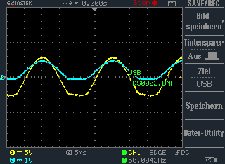
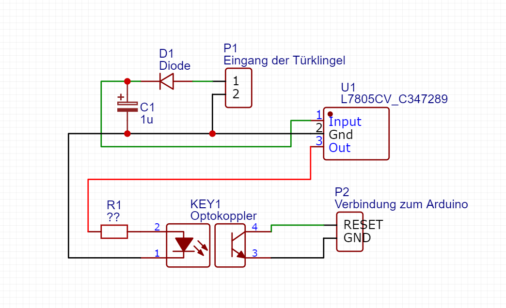
Diese wird mit einem Gleichrichter gleichgerichtet, also in eine Gleichspannung verwandelt (siehe Bild 1). Diese Gleichspannung aktiviert einen Optokoppler. Mehr dazu kann man dem Schaltplan entnehmen (siehe Bild 2). Dadurch, dass der Optokoppler einen Kurzschluss zwischen GND und RESET des ESP erzeugt, wacht der ESP auf und sendet ein Signal per MQTT an den Server. Dabei schickt er auch noch seine BatteryVoltage (eigentlich CORE-Spannung, da ich aber nicht Vin nutze, sondern direkt 3.3V speise ist das egal) mit. Dieser wurde vorher in den Deepsleep versetzt. Das Batteriefach welches ich nutze, hat leider einen Vorwiederstand, dieser ist für uns aber nur hinderlich und wird überbrückt. Der Code ist auch auf Github verfügbar.

Bild 1 (Gelb: Klingeltrafo, Blau: Nach dem Gleichrichter)
schematicV2 - Schaltplan
Bild 2 (Der Schaltplan)

Um kurz meinen Code zu erklären: Zuerst wird der ADC (AnalogDigitalConverter) auf “ADC_VCC” gesetzt, das bedeutet das der ADC die interne CPU-Spannung misst. Im Abschnitt “WiFi Access Point” müssen die WLAN Anmeldedaten eingegeben werden. Also WLAN_SSID muss die WLAN SSID sein, WLAN_PASS muss das WLAN-Passwort sein. Wichtig ist auch der “MQTT Server Setup” Abschnitt. Dort müssen die MQTT Serveranmeldedaten eingegeben werden. In Feeds werden zwei Feeds definiert, einmal photocell, dieser wird auf 1 gesetzt wenn es klingelt, battery sendet den Batterieladezustand.

Der Code

ADC_MODE(ADC_VCC);

#include <ESP8266WiFi.h>
#include "Adafruit_MQTT.h"
#include "Adafruit_MQTT_Client.h"

/************************* WiFi Access Point *********************************/

#define WLAN_SSID       ""
#define WLAN_PASS       ""

/************************* MQTT Server Setup *********************************/

#define AIO_SERVER      "server"
#define AIO_SERVERPORT  1883                   // use 8883 for SSL
#define AIO_USERNAME    ""
#define AIO_KEY         ""

/************ Global State (you don't need to change this!) ******************/

// Create an ESP8266 WiFiClient class to connect to the MQTT server.
WiFiClient client;
// or... use WiFiFlientSecure for SSL
//WiFiClientSecure client;

// Setup the MQTT client class by passing in the WiFi client and MQTT server and login details.
Adafruit_MQTT_Client mqtt(&client, AIO_SERVER, AIO_SERVERPORT, AIO_USERNAME, AIO_KEY);

/****************************** Feeds ***************************************/


Adafruit_MQTT_Publish photocell = Adafruit_MQTT_Publish(&mqtt, "/klingel");
Adafruit_MQTT_Publish battery = Adafruit_MQTT_Publish(&mqtt, "/battery");


/*************************** Sketch Code ************************************/

void MQTT_connect();

void setup() {
  Serial.begin(115200);
  Serial.setTimeout(2000);
  delay(10);

  Serial.println(F("MQTT Tuerklingel"));

  // Connect to WiFi access point.
  Serial.println(); Serial.println();
  Serial.print("Connecting to ");
  Serial.println(WLAN_SSID);

  WiFi.begin(WLAN_SSID, WLAN_PASS);
  while (WiFi.status() != WL_CONNECTED) {
    delay(500);
    Serial.print(".");
  }
  Serial.println();

  Serial.println("WiFi connected");
  Serial.println("IP address: "); Serial.println(WiFi.localIP());
}

uint32_t x = 0;

void loop() {
  yield();
  MQTT_connect();

  Serial.print(F("\nSENDING door change "));
  Serial.print(1);
  Serial.print("...");
  if (! photocell.publish(1)) {
    Serial.println(F("Failed"));
  } else {
    Serial.println(F("OK!"));
  }
  Serial.print(F("\nSENDING battery "));
  Serial.print(ESP.getVcc());
  Serial.print("...");
  if (! battery.publish(ESP.getVcc())) {
    Serial.println(F("Failed"));
  } else {
    Serial.println(F("OK!"));
  }
  delay(1000);
  Serial.print(F("\nSending RESET signal"));
  Serial.print("...");
  if (! photocell.publish(0)) {
    Serial.println(F("Failed"));
  } else {
    Serial.println(F("OK!"));
  }
  Serial.println(F("Going to sleep!"));
  delay(20);

  ESP.deepSleep(0);
}

// Function to connect and reconnect as necessary to the MQTT server.
// Should be called in the loop function and it will take care if connecting.
void MQTT_connect() {
  int8_t ret;

  // Stop if already connected.
  if (mqtt.connected()) {
    return;
  }

  Serial.print("Connecting to MQTT... ");

  uint8_t retries = 3;
  while ((ret = mqtt.connect()) != 0) { // connect will return 0 for connected
    Serial.println(mqtt.connectErrorString(ret));
    Serial.println("Retrying MQTT connection in 5 seconds...");
    mqtt.disconnect();
    delay(5000);  // wait 5 seconds
    retries--;
    if (retries == 0) {
      // basically die and wait for WDT to reset me
      while (1);
    }
  }
  Serial.println("MQTT Connected!");
}

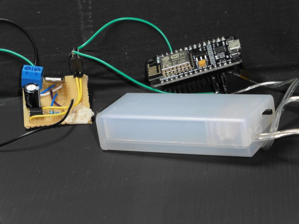
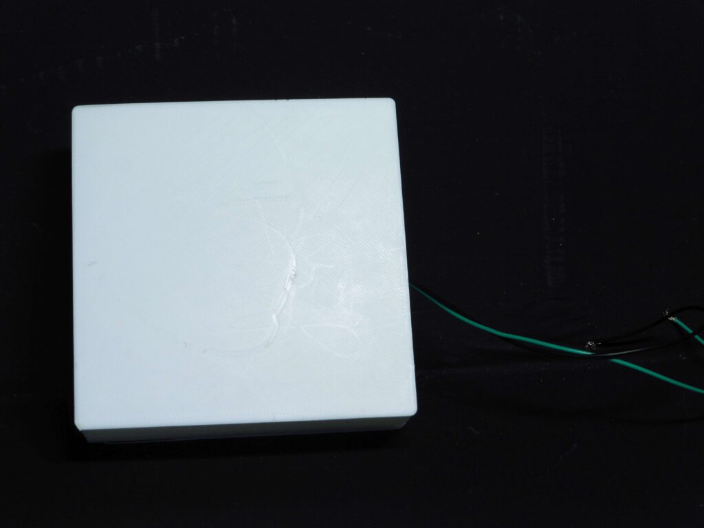
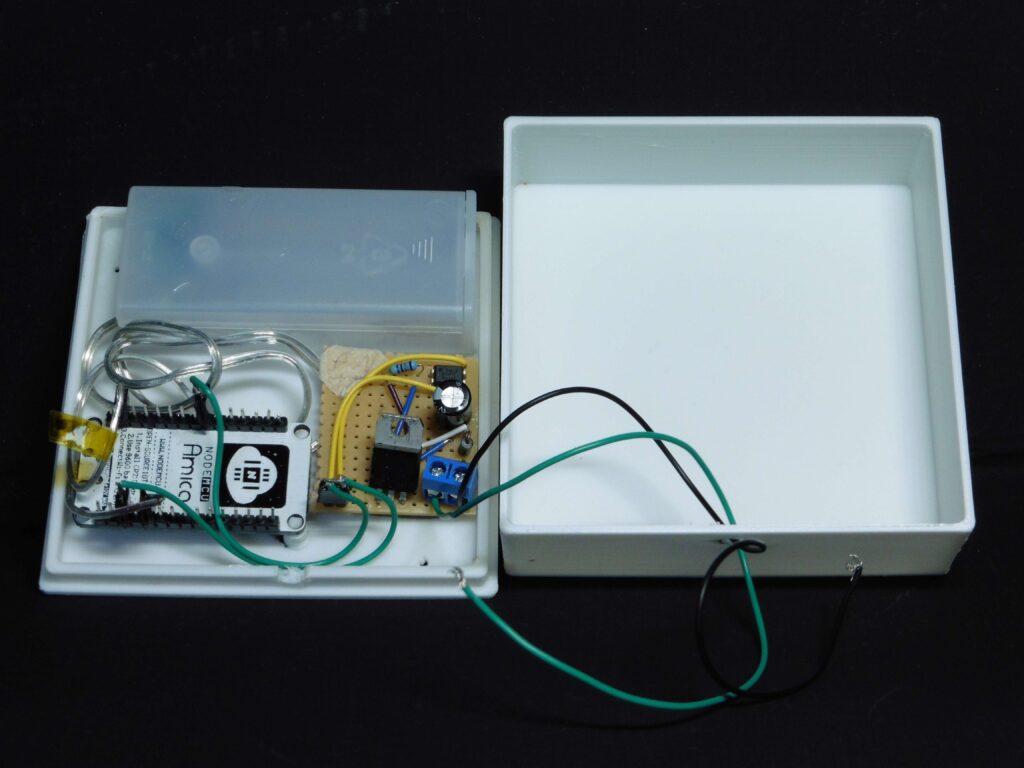
Zuletzt fehlte nur noch ein passendes Gehäuse. Die STL Datei des Gehäuses gibt es auch auf Github. An den Pfosten auf welchen der ESP8266 gesteckt werden sollte, musste erst die Feile etwas nachhelfen. Dann wurde noch ein 3mm dickes Loch in den Deckel gebohrt, um die Leitungen der Klingel durchlassen zu können. Zuletzt noch ein paar Bilder:

Nachtrag: Dieses Projekt macht nur wirklich Sinn wenn man eine ständige Stromversorgung hat und das WLan stabil ist. Ich nutze mittlerweile die HmIP-DSD-PCB von Homematic.

© 2024 Thegreydiamond

Theme by Anders NorenUp ↑