TheGreydiamonds Blog

Month: September 2021

Sending, Receiving and verifying messages sent over LoRa using RFM95W

In this blog post, I will be using an RFM95W LoRa chip together with an ESP8266/ESP32 to transmit (receive/send) data and check if this data is complete.

Preperations

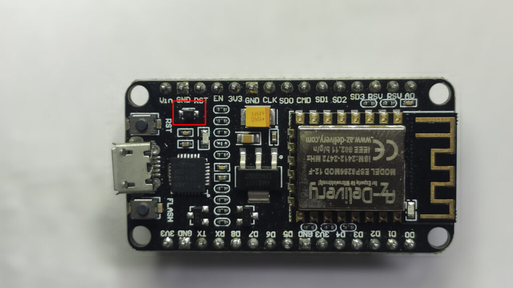
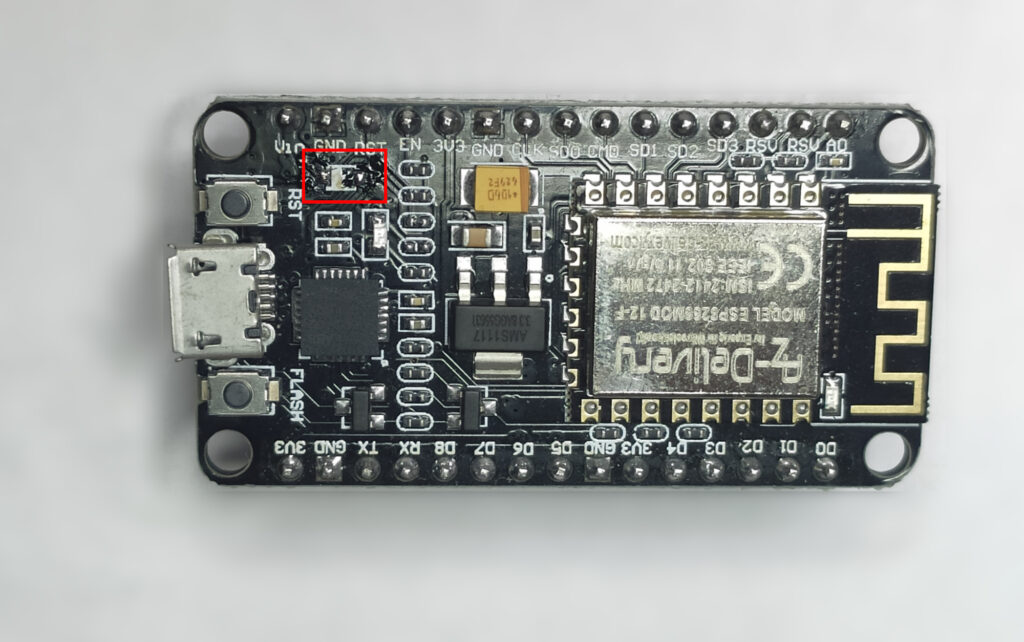
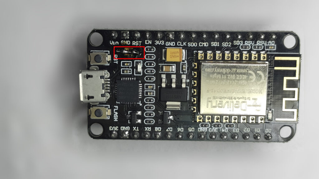
My first course of action was to get two ESPs ready to send/receive data via LoRa. If you have trouble or are looking for a dedicated tutorial have a look at these posts for the ESP32 and ESP8266. I have decided that my ESP8266 will send data and my ESP32 receive this data.

As a simple first test, I used the provided example sketches. This worked pretty well, I received my packets on the ESP32. After looking at it for a while I found a problem: RF has (like everything else) the problem of packet corruption, it doesn’t happen very often but when it does, it gets annoying.

The Problem

Our main problem is data corruption, my goal for this is to detect data corruption and ignore the received message. Let’s take an example: You have a simple LoRa node connected to a motion sensor, we send a data packet containing the battery state and the motion sensor’s state, like so:

0;1

The zero being the motion state (0, meaning false / no motion), and the 1 being the battery health (1, meaning true / healthy). Now let’s imagine there is a packet corruption and the first part (0;) gets removed, now our first item is a 1. If the receiver doesn’t notice the broken package, it might be that a false alarm gets triggered. After all the first bit, so motion, was true. This is the reason we need to check if a package is actually healthy.

My idea was to send the data and append some kind of hash to it. I will be using a sha1 hash for this, as ESPs can calculate this hash pretty easily, even though it’s a little overkill for this application. My new package will now look like this:

Actual data here;hash
Hello 4;a94a8fe5ccb19ba61c4c0873d391e987982fbbd3

Okay, after making the theory clear let’s implement it!

The implementation

Starting with my sending code, it looks like this:

Use the right frequencies for your region

If you adapt this code please check if you use the right frequency. Different regions use different frequencies for LoRa. Please check your local guidelines. Europe uses 868MHz (868E6). Update your LoRa.begin line! Here is a useful table by TTN.

#include <SPI.h>
#include <LoRa.h>
#include "Hash.h"

int counter = 0;
// - Pin configs - ESP32 -
// #define ss 5
// #define rst 14
// #define dio0 2

// - Pin configs - ESP8266 -
#define ss 4    // D2
#define rst  5 // D1
#define dio0 -1 // Disabled


void setup() {
  Serial.begin(115200);
  while (!Serial);
  delay(1000);

  Serial.println("LoRa Sender");
  // Setup LoRa transceiver module
  LoRa.setPins(ss, rst, dio0);
  if (!LoRa.begin(868E6)) {
    Serial.println("Starting LoRa failed!");
    delay(5000);
    Serial.println("Now waiting for Watchdog to restart");
    while (1);
  }else{
    Serial.println("Starting LoRa successful");
    }
  
}

// Sends a string every 5000ms (5 seconds)
void loop() {
  Serial.print("Sending packet: ");
  Serial.println(counter);

  // send packet
  LoRa.beginPacket();
  String result = sha1("hello " + String(counter)); // Creating the hash value for our string
  LoRa.print("hello ");
  LoRa.print(counter);
  LoRa.print(";");
  LoRa.print(result);
  LoRa.endPacket();

  counter++;

  delay(5000);
}

This will send our packets with the hash appended. For the next bit, we will need to receive the message and check if the supplied hash is correct.

#include <SPI.h>
#include <LoRa.h>
#include <Hash.h>
// - Pin configs - ESP32 -
#define ss 5
#define rst 14
#define dio0 2

// - Pin configs - ESP8266 -
// #define ss 4    // D2
// #define rst  5 // D1
// #define dio0 -1 // Disabled

// Taken from https://forum.arduino.cc/t/arduino-split-funktion-eines-strings/595753
String split(String s, char parser, int index) {
  String rs = "";
  int parserIndex = index;
  int parserCnt = 0;
  int rFromIndex = 0, rToIndex = -1;
  while (index >= parserCnt) {
    rFromIndex = rToIndex + 1;
    rToIndex = s.indexOf(parser, rFromIndex);
    if (index == parserCnt) {
      if (rToIndex == 0 || rToIndex == -1) return "";
      return s.substring(rFromIndex, rToIndex);
    } else parserCnt++;
  }
  return rs;
}

void setup() {
  Serial.begin(115200);
  while (!Serial);

  Serial.println("LoRa Receiver");
  LoRa.setPins(ss, rst, dio0);
if (!LoRa.begin(868E6)) {
    Serial.println("Starting LoRa failed!");
    delay(5000);
    Serial.println("Now waiting for Watchdog to restart");
    while (1);
  }else{
    Serial.println("Starting LoRa successful");
    }
}

void loop() {
  // try to parse packet
  int packetSize = LoRa.parsePacket();
  if (packetSize) {
    // received a packet
    Serial.print("Received packet '");

    // Create a string of the incoming message
    String message = "";
    while (LoRa.available()) {
      message += (char)LoRa.read();
    }
    Serial.print(message);
 
    String result = sha1(split(message, ';', 0)); // Take the first element, the raw message and hashing it
    String tempy = message;
    tempy.replace(split(message, ';', 0) + ";", ""); // Now replace the message so only the hash is left
    if (result == tempy) { // Is the hash the same?
      Serial.print(" Hash ok ");
    } else {
      Serial.print(" Hash fail, expectd hash ");
      Serial.print(tempy);
      Serial.print(" "); 
      Serial.print(split(message, ';', 1)); 
      Serial.print(" "); 
    }

    // print RSSI of packet
    Serial.print("' with RSSI ");
    Serial.println(LoRa.packetRssi());
  }
}

Using the hash library on ESP32

For some reason, the ESP32 does not implement the same hash functions as the ESP8266. Therefore I used this third party library to get the same functinality.

After running the code for a while I got this output on my receiver serial console. It worked! Sadly it’s pretty hard to break a package on purpose, but I checked it and this code works, however, I sadly don’t have a screenshot of a broken transmission.

This concludes my little experiment/project here, I have achieved my goal to detect broken transmissions and that’s it! I hoped this helped someone on their way.

Getting started with RFM95W, LoRa and ESP8266

In this blog post I will be introducing you to LoRa using the RFM95W module with an ESP8266, so let’s get started. I also wrote this article for the ESP32, read it here.

First, we should talk about what LoRa is and what it stands for. LoRa stands for Long Range and as the name suggests one of its main aspects is its considerable range. However, we need to make a distinction between LoRa and LoRaWAN. In this tutorial, I will be talking about LoRa. LoRaWAN adds another layer of authentification. Services like TheThingsNetwork (TTN) use LoRaWAN. However, LoRa is easier to use and understand for this tutorial.

Hardware used / Preparation

For this tutorial, I will be using an RFM95W module with an ESP8266. This is a bit tricky because there are some weird road bumps. The RFM95W is our LoRa communication chip. I’ve got my ESP from the german seller AZ-Delivery (I’m not affiliated with them in any way nor do I get any money from them for mentioning their name). My RFM95W comes from Amazon.

For this, I will assume that your Arduino IDE is set up to work with ESP8266s. If not here is a tutorial to do it.

Wiring

The wiring diagram

If you have a different ESP you can check the documentation supplied below for further details.

Now get started, for real

As a first step build up the setup shown above. Next, you need to install the LoRa Libary by Sandeep Mistry. More documentation is available here.

This code is actually the library’s example code modified to give a little more output.

Use the right frequencies for your region

Different regions use different frequencies for LoRa. Please check your local guidelines. Europe uses 868MHz (868E6). Update your LoRa.begin line! Here is a table by TTN.

#include <SPI.h>
#include <LoRa.h>

int counter = 0;
// - Pin configs -
#define ss 4    // D2
#define rst  5 // D1
#define dio0 -1

void setup() {
  Serial.begin(115200);
  while (!Serial);
  delay(1000);

  Serial.println("LoRa Sender");
  // Setup LoRa transceiver module
  LoRa.setPins(ss, rst, dio0);
  
  if (!LoRa.begin(868E6)) {
    Serial.println("Starting LoRa failed!");
    while (1);
  }else{
    Serial.println("Starting LoRa successful");
    }
  
}

// Sends a string every 5000ms (5 seconds)
void loop() {
  Serial.print("Sending packet: ");
  Serial.println(counter);

  // send packet
  LoRa.beginPacket();
  LoRa.print("hello ");
  LoRa.print(counter);
  LoRa.endPacket();

  counter++;

  delay(5000);
}

Information

I was unable to make the DIO0 work. This is why this sketch does not use it. Be aware!

I’ve had some issues using the code out-of-the-box. Some problems are due to the code lacking a lot of verbosity and some are due to user problems. The code above fixes one of the issues, verbosity. The other one is addressed below.

Tip

Please note that the library expects GPIO pins, not D pins. More information is available here.

After changing your frequencies and making sure that you use the right board, hit the upload button. After the upload is done open your serial console, select 115200 baud. Then you should see this output:

A arduino serial output window.
The serial output

And finally, your ESP is sending LoRa. Some of the items I need for receiving are stuck in shipping this has to wait for another day. However, below is a short paragraph for those who already own an SDR.

Does this even work? For people with SDRs

This paragraph is made for people who own SDRs (SoftwareDefinedRadio). For this, I’m using a VM running ParrotOS. This image comes preinstalled with SDR++. GNUradio and a bunch of extensions for GNUradio. These extensions also contain gr-lora, which I will be using here. Following this tutorial in the wiki, you should be able to set up your workspace to receive LoRa messages. Please also remember to use the right frequency. The results looks something like this:

With this setup, I was able to use a pretty good range, even though I only used a so-called random wire antenna. This also shows how some packets are missing some data. This shows why you should always use the hash numbers to verify that the received packet is healthy. I will be talking about hashes sometime in the future.

The result as seen in SDR++

I hope I could get you on your way into the interesting world of LoRa.

Fixing a broken ESP8266 (NodeMCU)

We’ve all done it before, accidentally shorting Vin (Voltage input) and GND (Ground) on an ESP8266. I have done it as well thinking: How should this break an ESP8266? It turns out by destroying the reverse polarity diode. These are not my findings btw, by these people figured it out. But let’s get to work. Here is the current state:

Broken diode marked with a red rectangle

The thing marked with a red box is the broken diode. This is the thing that needs to be fixed. First step: Remove it.

In the next step, we will replace it with a new diode called wire.

The diode replaced with a wire

This fixed my broken ESP8266 and brought it back to life. I hope someone can use this.

Cloudflare Rocket loader or why my Nextcloud won’t work

This article is about Cloudflare Rocket loaders passion to break Nextcloud (and apparently PhpMyAdmin for some people) and how to fix it.

I have installed Nextlcoud for some testing purposes some time ago. As a side note; Yes, I’m using Cloudflare for DNS. And was surprised by Nextcloud’s clean UI, consisting of only the logo and a background image.

A very clean UI

I know one of the last updates overhauled Nextclouds UI, but this is a little too clean, even in my taste. To diagnose the issues I swiftly opened the Javascript console hidden away in the inspect element dialogue. One of the major error messages I saw was the browser being unable to load a library called “RocketLoader”. After some searching, I found out that others have also run into this problem before, but Nextcloud does not use RocketLoader. After going through Cloudflare’s Speed setting in boredom one day I saw an option titled “Enable Cloudflare Rocket Loader”, which was enabled. I turned the ticked box off, and yes a few minutes later Nextcloud worked again!

Tl;Dr

Go into your domains Cloudflare setting, then choose Speed and go to “Optimization”, disable the Rocket Loader™ option. Your service should start working properly again.

Getting started with RFM95W, LoRa and ESP32

In this blog post I will be introducing you to LoRa using the RFM95W module with an ESP32, so let’s get started. I also wrote a tutorial for the ESP8266.

First, we should talk about what LoRa is and what it stands for. LoRa stands for Long Range and as the name suggests one of its main aspects is its considerable range. However, we need to make a distinction between LoRa and LoRaWAN. In this tutorial, I will be talking about LoRa. LoRaWAN adds another layer of authentification. Services like TheThingsNetwork (TTN) use LoRaWAN. However, LoRa is easier to use and understand for this tutorial.

Hardware used / Preparation

For this tutorial, I will be using an RFM95W module with an ESP32. The RFM95W is our LoRa communication chip. I’ve got my ESP from the german seller AZ-Delivery (I’m not affiliated with them in any way nor do I get any money from them for mentioning their name). My RFM95W comes from Amazon.

For this, I will assume that your Arduino IDE is set up to work with ESP32s. If not here is a tutorial to do it.

Wiring

The wiring diagram

If you have a different ESP you can check the documentation supplied below for further details.

Now get started, for real

As a first step build up the setup shown above. Next, you need to install the LoRa Libary by Sandeep Mistry. More documentation is available here.

This code is actually the library’s example code modified to give a little more output.

Use the right frequencies for your region

Different regions use different frequencies for LoRa. Please check your local guidelines. Europe uses 868MHz (868E6). Update your LoRa.begin line!

#include <SPI.h>
#include <LoRa.h>

int counter = 0;
// - Pin configs -
#define ss 5
#define rst 14
#define dio0 2

void setup() {
  Serial.begin(115200);
  while (!Serial);
  delay(1000);

  Serial.println("LoRa Sender");
  // Setup LoRa transceiver module
  LoRa.setPins(ss, rst, dio0);
  
  if (!LoRa.begin(868E6)) {
    Serial.println("Starting LoRa failed!");
    while (1);
  }else{
    Serial.println("Starting LoRa successful");
    }
  
}

// Sends a string every 5000ms (5 seconds)
void loop() {
  Serial.print("Sending packet: ");
  Serial.println(counter);

  // send packet
  LoRa.beginPacket();
  LoRa.print("hello ");
  LoRa.print(counter);
  LoRa.endPacket();

  counter++;

  delay(5000);
}

I’ve had some issues using the code out-of-the-box. Some problems are due to the code lacking a lot of verbosity and some are due to user problems. The code above fixes one of the issues, verbosity. The other one is addressed below.

Tip

While trying to get this running I’ve run into an issue where the code returned “Starting LoRa successful”, however, no data got sent. Make sure to use the correct board, check with your manufacturer what board you should use. Different boards have different pinouts.

After changing your frequencies and making sure that you use the right board, hit the upload button. After the upload is done open your serial console, select 115200 baud. Then you should see this output:

A arduino serial output window.
The serial output

And finally, your ESP is sending LoRa. Some of the items I need for receiving are stuck in shipping this has to wait for another day. However, below is a short paragraph for those who already own an SDR.

Does this even work? For people with SDRs

This paragraph is made for people who own SDRs (SoftwareDefinedRadio). For this, I’m using a VM running ParrotOS. This image comes preinstalled with SDR++. GNUradio and a bunch of extensions for GNUradio. These extensions also contain gr-lora, which I will be using here. Following this tutorial in the wiki, you should be able to set up your workspace to receive LoRa messages. Please also remember to use the right frequency. The results looks something like this:

With this setup, I was able to use a pretty good range, even though I only used a so-called random wire antenna. This also shows how some packets are missing some data. This shows why you should always use the hash numbers to verify that the received packet is healthy. I will be talking about hashes sometime in the future.

The result as seen in SDR++

I hope I could get you on your way into the interesting world of LoRa.

© 2024 Thegreydiamond

Theme by Anders NorenUp ↑