TheGreydiamonds Blog

Year: 2025

Just another Bindicator

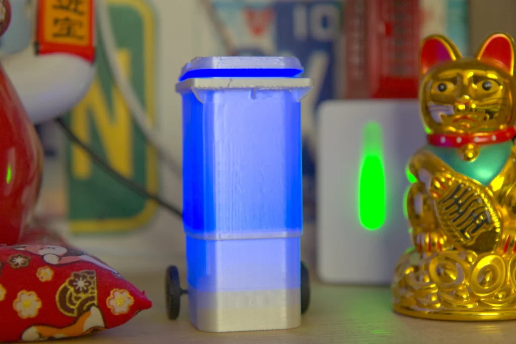
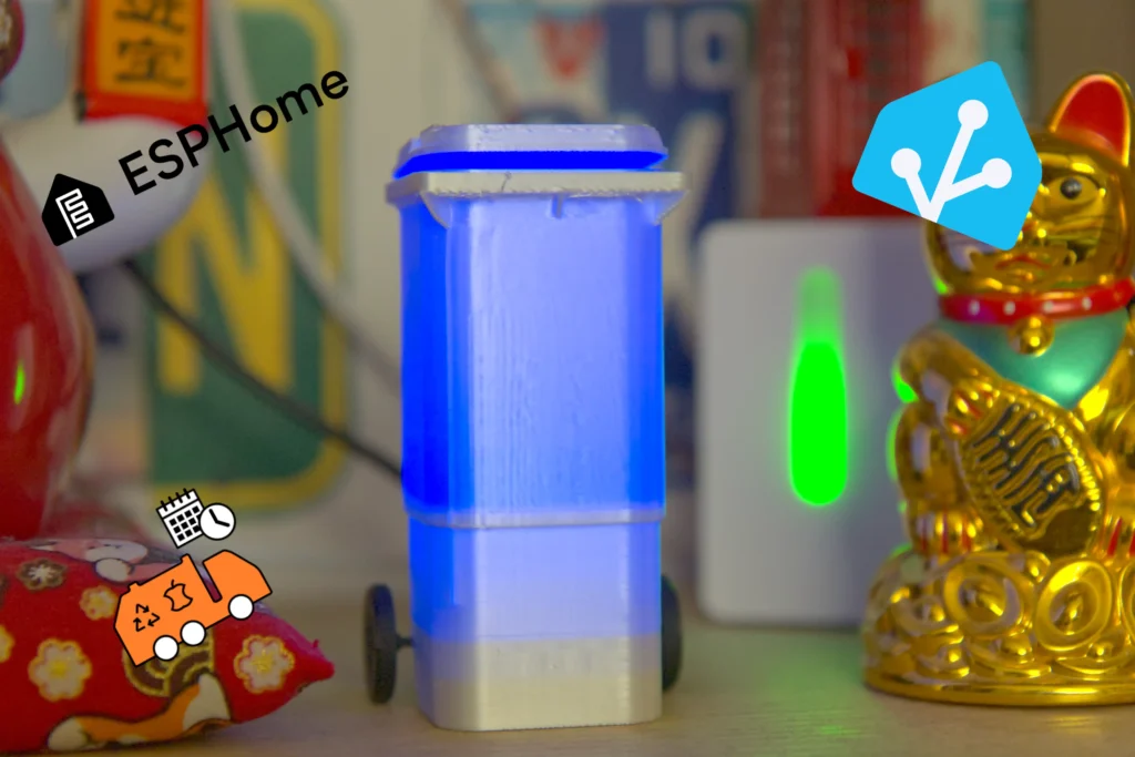
While mindlessly scrolling Reddit, I found a project on the r/homeassistant subreddit which piqued my interest. A bin indicator (or indicator for short) that lit up a miniature wheelie bin whenever it is time to take out the trash. Taking inspiration from Dean Fourie’s Bindicator I set out to make my one.

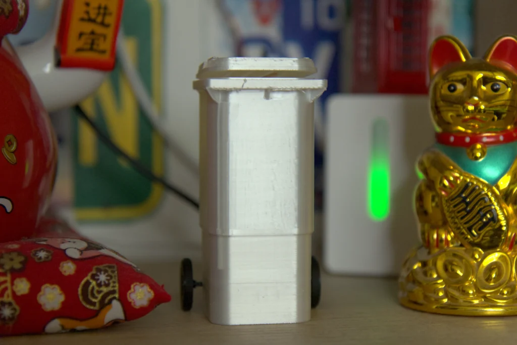
The very first step was to find a wheelie bin model I liked. After scouring platforms like Thingiverse and Makerworld, I settled on this model by “JAV-3D” as it resembled our bins the most. I’ve printed it on my Bambu Labs A1 using white silk filament.

Using the basic tools BambuStudio provides, I added a hole for the USB-C plug to fit through as a last-minute addition.

Brainnnsss…

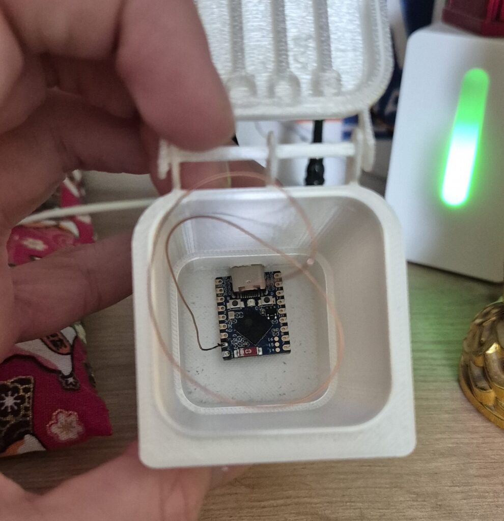
Next came the more interesting part, the heart and soul of this project: the electronics! I’ve opted to use an ESP32-S3-Zero made by Waveshare for two reasons:

  • I had it lying around
  • It features an integrated WS2812 pixel

This reduced the amount of extra hardware I needed. The only other thing I added was a bit of enamelled copper wire to GPIO 5. This will serve as a touch button which works through the lid of the bin. When you tap the top, the light will dim down to show that you have “acknowledged” the notification (aka you brought the trash out).

As I’m already actively using Home Assistant for my smart home, it made sense to opt for ESPHome as my firmware base. I used the online tool for flashing ESPHome. and commissioned it into my network. The configuration is fairly straightforward:

esphome:
  name: esphome-bindicator
  friendly_name: ESPHome Web - Bindicator
  min_version: 2025.5.0
  name_add_mac_suffix: false

esp32:
  board: esp32-s3-devkitc-1
  framework:
    type: esp-idf

# Enable logging
logger:

# Enable Home Assistant API
api:

# Allow Over-The-Air updates
ota:
- platform: esphome

web_server:
  port: 80

wifi:
  ssid: !secret wifi_ssid
  password: !secret wifi_password

  # Enable fallback hotspot if WiFi connection fails
  ap:

light:
  - platform: esp32_rmt_led_strip
    rgb_order: RGB
    pin: GPIO21
    num_leds: 1
    chipset: ws2812
    name: "Binlight"
    id: "binlight"
    effects:
    - pulse:
        name: "Blink Fast"
        transition_length: 250ms
        update_interval: 250ms
        min_brightness: 8%
        max_brightness: 100%

    - pulse:
        name: "Blink Slow"
        transition_length: 2s
        update_interval: 2s
        min_brightness: 40%
        max_brightness: 100%

esp32_touch:
  setup_mode: false
  measurement_duration: 0.25ms  # Much lower than the 8ms default
  sleep_duration: 0.5ms

binary_sensor:
  - platform: esp32_touch
    name: "Binlight Ack Btn"
    pin: GPIO5
    threshold: 1000

This config uses the esp32_rmt_led_strip component to drive the pixel internally connected to GPIO21, and adds two effects. It also initialises the touch component. If you use a different ESP32 board, I recommend you check the touch component documentation. I needed to change some values for it to work at all.

Home Assistant Integration

Now, only one component was missing: The collection schedule data. My local waste collection company is supported by the awesome “Waste Collection Schedule” integration for Home Assistant. I only care about two kinds of garbage: paper and packaging (“gelber sack” = “yellow trash” in German). For each, I configured a sensor with this config:

Format: Next
Value Template: {{value.daysTo}}
Type: “Papierabfall” (or whatever you want)

Last but not least, I created a new automation. My triggers were quite simple:

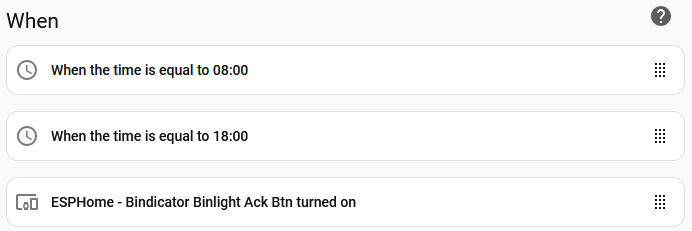
Two time triggers (“update” times) and a trigger for handling the acknowledgement.

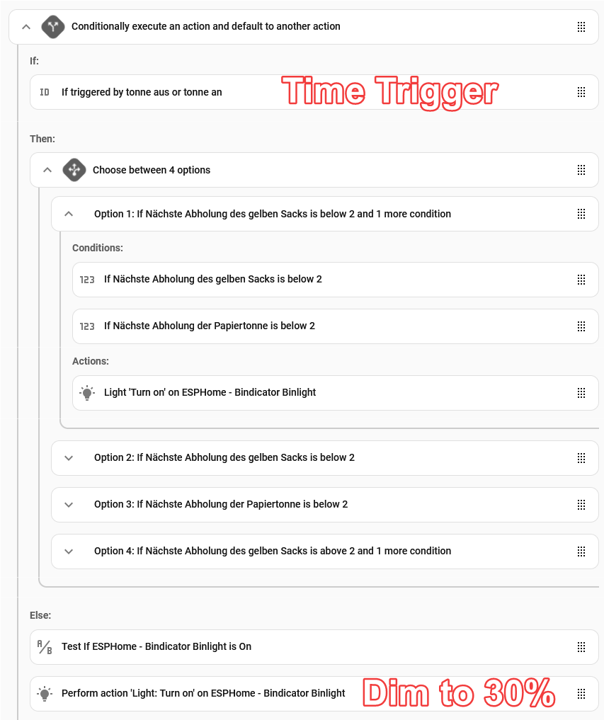
The logic was a little more complex. When it is time to update the state, I check which trash type is next (or if both fall on the same day) and turn on the light accordingly. If both types are more than 2 days away, the light gets simply switched off.

When the touch button gets triggered, I dim the indicator to 30% (only if it was on in the first place)

Final result

After an afternoon of tinkering, I was happy with my result. Let me know down in the comments if you have something similar for your smart home! Now enjoy a few photos and a video demo of the final result:

Learn more about my Smarthome projects

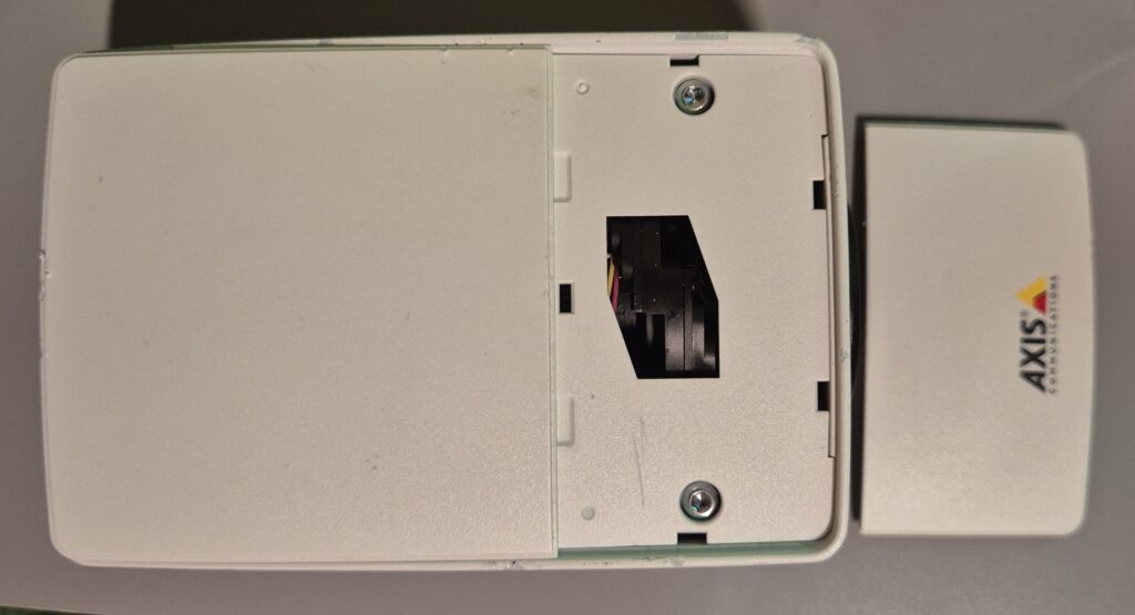
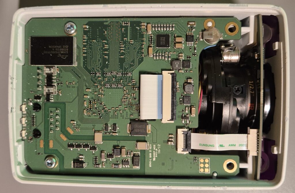
How to open an AXIS M1145-L CCTV camera

In this short post I want to share a few photos and tips on how to open an AXIS M1145-L CCTV camera. I recently had a problem where the camera was unable to properly focus after being dropped. There are no obvious screws visible.

To open the camera first unclip the front most cover of the top shield. This will uncover two screws:

Unscrew them and then unclip the bigger piece at the back. After doing that you will be able to access the PCB and lens-mechanism:

This was acctually all I needed to do, after closing the case again my focus was back to normal.

I hope this little article helped you. Leave a comment if it helped you!

Building a Clansman Microphone connector

Sometime ago an Avon S10 gasmask came into my possesion. I personally think it looks rather cool. But that is not the point of this post. The mask has a plethora of features, from drinking tubes to very thought-thru air circulation. But more importantly for this article: the S10 has a “secondary speech module” on its side, where you are able to add an external microphone for use with radios or other means of communication.

A clansman microphone module with a short wire attached to it. The microphone module is made from black plastics, the membrane is green with a red stripe across.
The S10 clansman microphone

The microphone itself clips onto the side of the S10 fairly easily. Its connector, however, is a little trickier. It uses a British military standard called “Clansman”, which contains a set of three pins in a locking connector. Procuring the microphone module was fairly simple, I got it from eBay for cheap. Finding a receptacle for it, however, was not. So it was time to make one!

A top down view of a worn-down connector with three pins in the center. The casing is in a dark military green.
A top-down view of the clansman connector

After stuffing some jumper cables in the connector, just to check if the microphone even worked. Which it did! (more about that below) I decided to 3D print a fitting connector to ruggedise the setup a little more:

A simple 3D rendering showing a plastic part with three extrusion.

This design allows you to stuff three normal jumper cables in, add some hot glue and shrinkwrap. In my experience it works well, I’ve had no issues yet.

Electrical setup

The electrical setup is very simple. You have one ground and two pins for the microphone. Building an adapter to convert it to regular audio cabling is a trivial task.

Pinout of the Clansman microphone, if anyone should need it:

A simple image showing the pinout of the clansman connector. Three pins are shown. The pins at one and four o'clock are marked with "microphone". Another one at eight is marked with "ground".
Top-down view of the pinout

A few more photos

A styrofoam head wearing an S10 mask with tinted lenses. The clansman microphone is attached to the mask and a black tactical helmet.

Using Cisco SIP Phones with OpenConnect VPN Server

Most Cisco SIP Phones support connecting to a VPN server directly which makes it easy to connect phones which are outside the usual network. When connecting to a VPN they utilize Ciscos’ AnyConnect protocol, which usually requires a costly license to be used. However, due to the efforts of the team behind the OpenConnect VPN Server that is no longer the case (and has been for quite a while now). In this guide, I want to show you how to set up your server and phone to be able to properly communicate. There are a few bits of information and discussion out there, however, I was unable to find something like a complete guide. So let’s get started!

Requirements

A few components are required to get this up-and-running. I also assume that the reader has basic understanding of network and the usage of linux.

  • Cisco SIP Phone (I used an 8851 on MPP firmware)
  • PBX Server (for the phone to log into, I used FreePBX)
  • VM/Server to run OcServ
  • Public domain with SSL certificate

Preparations

I recommend you first build a simple setup to evaulate if the SIP itself works before introducing more complexity. This however is out of scope for this article as there are many guides on the internet on how to setup FreePBX and Cisco Phones.

This guide is based on Debian systems. This leads to one issue: the ocserv version currently shipped with Debian is outdated and won’t work with the Cisco Phones, for that reason, we need to compile a newer version of ocServ. For this guide4 we will use ocServ 1.3.0. Here’s how:

  1. Grab the Tarball “Package” file from the official ocServ gitlab
  2. Unpack it on your VPN server (tar -xvf ocserv-1.3.0.tar.xz)
  3. Enter the newly unpacked directory (cd ocserv-1.3.0)
  4. Follow the basic compilation instructions (./configure && make)
  5. Run sudo make install to install the ocserv package

Configuring ocServ

In most cases you want to run OcServ as a service, meaning it will restart on failure and start on bootup. For my setup, I use this Systemd service file in /etc/systemd/system/ocserv.service

[Unit]
Description=OpenConnect SSL VPN server
Documentation=man:ocserv(8)
After=network-online.target

[Service]
PrivateTmp=true
PIDFile=/run/ocserv.pid
Type=simple
ExecStart=/usr/local/sbin/ocserv --log-stderr --foreground --pid-file /run/ocserv.pid --config /etc/ocserv/ocserv.conf
ExecReload=/bin/kill -HUP $MAINPID

[Install]
WantedBy=multi-user.target

It is also recommended to create a service user for ocserv to use (which I already had, because I previsuouly tried to use the apt-shipped version of ocserv).

After setting ocserv up as a service we need to change it’s configuration file found in /etc/ocserv/ocserv.conf.

First of all, you have to decide on an authentication strategy, for most test cases “plain” is fine. If you want to run a more complete and productive setup it is however recommended you use PAM, radius or similar services. For this guide, I will use plain auth due to its simplicity. That’s why I enable this line in the config:

auth = "plain[passwd=/etc/ocserv/ocpasswd]"

If you created a service user beforehand it is recommended to set run-as-group and run-as-user:

run-as-user = ocserv
run-as-group = ocserv

As mentioned you need a valid TLS certificate to be able to properly run the server. How you get this heavily depends on your setup and is out-of-scope for this guide. A good starting point might be Let’s Encrypt. Your certificates need to be configured as well, just like your domain:

server-cert = /opt/certs/example.org/fullchain.pem
server-key = /opt/certs/example.org/privkey.pem
default-domain = vpn.example.org

Make sure the network configuration fits in with your own setup, which requires setting ipv4-network to an address space for clients to use. You also need to configure a valid DNS-server and routes which will allow connection to your PBX server.

There are also a few phone-specific changes you should make. First of all: turn compression off, as it might mess with latency. You also need to enable cisco-client-compat.

compression = false
cisco-client-compat = true

Now restart and enable the ocserv service and your OpenConnect server is ready to go:

sudo systemctl enable ocserv && systemctl restart ocserv

Setting up a user

To create a plaintext user run the command ocpasswd USERNAME and enter your password when prompted.

Testing the connection

If you want to make sure that you properly set up your server and certificate you can use the openconnect utility (the one from apt works well here). Simply type your server address in and you should see a user prompt:

Setting up the phone

This section might differ from model to model and MPP / non-MPP firmware. At the time of writing this I run my CP-8851 on the MPP firmware 12.0.7.

As a very first step, we need to upload a custom CA to the phone, as the default CAs shipped with the current firmware almost exclusively include Cisco CAs. (A complete list can be found here). Which CA you need to upload depends on your root certificate. For Let’s Encrypt you need either ISRG Root X1 or X2. These root CAs can be downloaded from the Let’s Encrypt website here. You need to get them in the “pem” format:

Getting them on the phone can be a little tricky, I used the Windows utility tftpd64 which has proved itself useful in the past. You simply need to place the .pem file into the “Current Directory” folder (1) and select the proper server interface (2) from the dropdown.

Now we need to tell the phone where to find a new CA. Visit https://yourphoneip/admin/advanced then go to Voice > Provisioning > CA Settings. Then enter tftp://yourpcip/isrg-root-x1-cross-signed.pem (or isrg-root-x2-cross-signed.pem). After clicking Submit All Changes the phone should pull a new certificate from your tftp server. To confirm a successful download you can head to Info > Download Status and check for “Custom CA Status”. The Custom CA Info should read something like: Installed - /C=US/O=Internet Security Research Group/CN=ISRG Root X1

Now, that the CA is properly setup, configureing the VPN is a breeze. Head to Voice > System > VPN Settings and enter your server domain, username and password. After configuring these settings press Submit All Changes.

First test flight

On your Cisco Phone, press the applications button , then select 5 Network Configuration > VPN settings. Then scroll down to “Enable VPN connection” and press the naviagation cluster (big round button). The phone should then connect to the VPN and restart. After rebooting a globe with lock icon should be shown in the top right corner which indicates a proper connection.

Conclusion

You successfully setup a connection to your own VPN, congratulations! If you want to connect to your VPN on phone startup, you should enable that option.

If you want to learn more about FreePBX and Asterisk I recommend you check out my other posts on the topic:

© 2025 Thegreydiamond

Theme by Anders NorenUp ↑